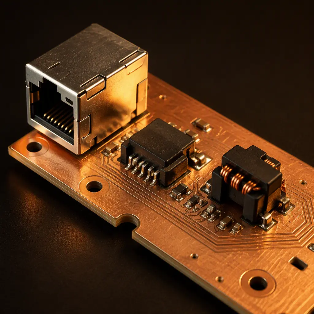
Every copper Ethernet port sits behind a small component that most engineers treat as a black box: the LAN magnetics module. It is simultaneously an isolation barrier, a common-mode filter, an impedance transformer, and — in Power over Ethernet — the part that feeds DC power onto the data pair. When a port fails EMC or shows intermittent link, the magnetics are almost always implicated, yet they rarely get the design attention they deserve. At Huaxing PCBA we assemble 8 SMT lines of boards a day, and the stacked 0.3 mm pitch / 0201 / X-ray inspection capability means we see both ends of this problem: design mistakes that show up as field returns, and the manufacturing signals that catch them.
This guide is about the magnetics component itself — not the PHY chip. If you need the PHY-side layout, decoupling and clocking, see our Ethernet PHY design guide. Here we focus on the transformer, the choke, the isolation rating, and how a contract manufacturer should help you verify it. We build IATF 16949 and ISO 9001 certified boards with 0.3 mm pitch and 0201 placement, so precision magnetics placement and inspection are squarely in our lane.
What the LAN Magnetics Module Actually Does
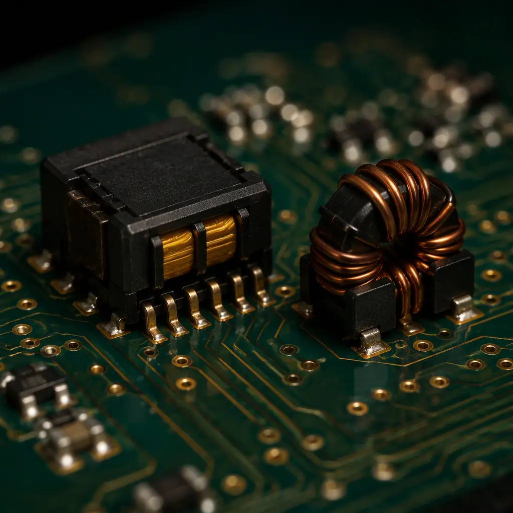
A copper PHY is referenced to the local ground of its own device. The cable side is referenced to the remote device's ground, which may be several volts or several hundred volts away. The magnetics bridge that potential difference safely while passing the differential signal through. In a 10/100/1000BASE-T module these are the jobs:
| Function | Implemented by | Why it matters |
|---|---|---|
| Isolation | Isolation transformer (1:1 or 1:1.41) | Blocks DC and common-mode voltage; safety duty for the 1500 Vrms barrier |
| Common-mode rejection | Centre-tap + common-mode choke | Rejects cable noise and reduces emissions |
| Impedance match | Turns ratio + winding design | 100 Ω differential throughout the 1–100 MHz band |
| Common-mode termination | Bob Smith termination | Shields common-mode energy at the cable end |
| PoE power injection | Centre-tap feeding the PSE/PD power | Delivers power without disturbing the data path |
The fault is that these are coupled functions. Change the turns ratio to squeeze a little more margin and you shift the common-mode rejection. Choose the cheapest choke and the emissions test finds you out. So the design decision is a balancing act, and it is worth understanding each knob. For the full signal-integrity context around the port, see our PCB signal integrity guide.
Isolation Voltage, Creepage and the Safety Barrier
This is the place manufacturing and certification meet. The IEEE 802.3 standard calls for a 1500 Vrms isolation (historically 1.5 kV, with 2.25 kV / 3 kV variants for industrial and medical parts), and that rating is only real if the magnetics module itself is rated for it and the board around it keeps the required creepage and clearance. A part that says 1500 Vrms on the datasheet fails in 400V-to-ground systems if you route a noisy plane under it or crowd the pads.
Pick the correct isolation class
Basic insulation for a typical LAN port (1500 Vrms), reinforced for industrial and mains-adjacent, up to 3 kV for medical per IEC 60601. Over-specifying adds cost; under-specifying is a compliance and reliability hazard. Match the magnetics isolation to the safety certification you are targeting.
Give the barrier real creepage
Keep the primary and secondary sides separated by the clearance the standard requires — for 1500 Vrms working, a practical figure is 2.0–3.0 mm and more across slots when contamination is likely. If your board goes into a harsh environment, a physical isolation slot is the reliable answer. This feeds directly into the EMC/EMI design of the whole system.
Keep the magnetics footprint clean underneath
Never route the high-speed differential pairs underneath the magnetics can. Copper under the transformer couples noise straight into the windings and destroys the common-mode rejection that the part is there to provide. Keep the reference plane continuous where you can, and never run a switching or clock trace under the isolation barrier.
Turns Ratio and the 100Ω Differential Path
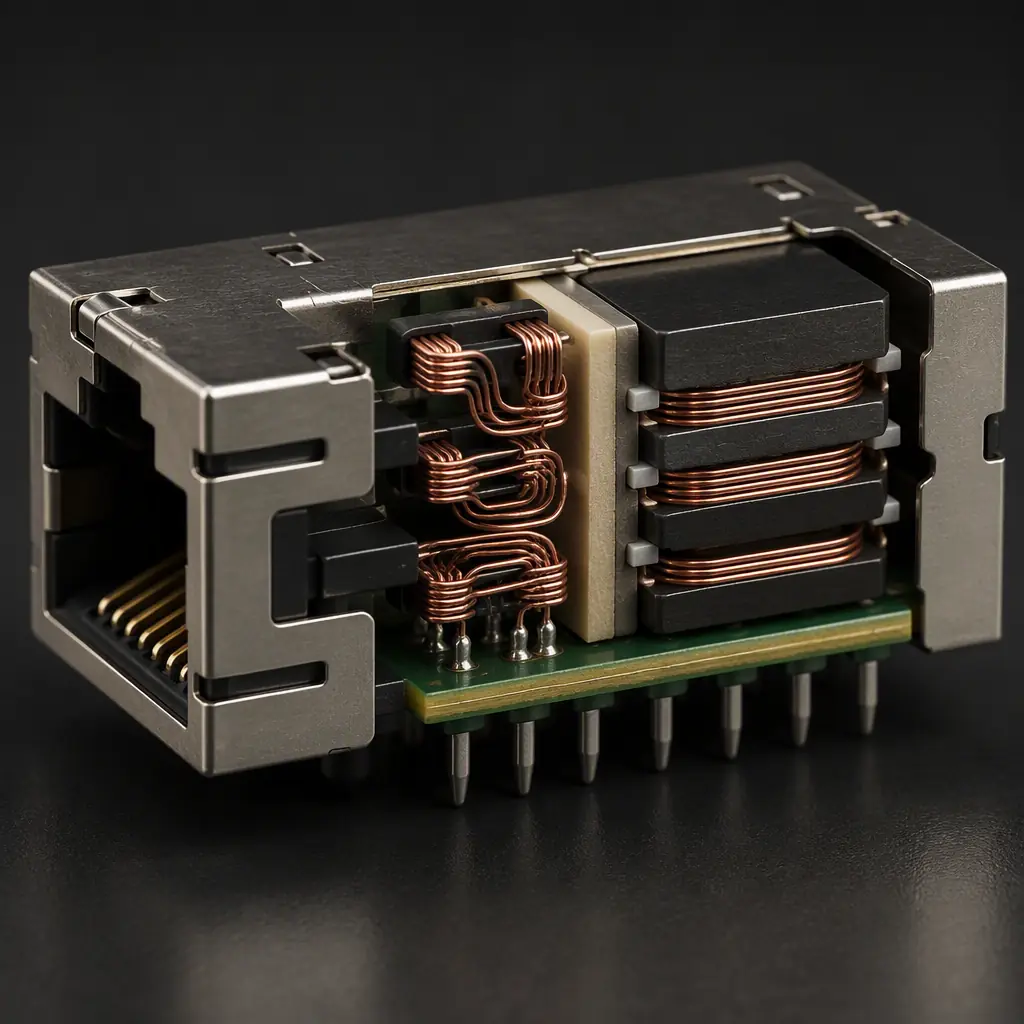
For copper Ethernet the transformer is nominally 1:1, which converts the PHY's transmit/receive signal at the correct internal impedance to the 100Ω differential cable. Some 10BASE-T legacy parts use a 1:1.41 or 1:2 ratio to step up the transmit signal; the important thing is that the ratio you choose must give you the right S-parameters across the whole 100 MHz band, not just at 1 MHz. A part with a good return-loss figure at low frequency can still fall over at 100 MHz.
Watch these three numbers on every magnetics datasheet, and ask your assembler to verify them on the production lot:
| Parameter | Typical 1000BASE-T | What a change in it does |
|---|---|---|
| Insertion loss | ≈0.5–1.5 dB over band | Buys or costs you link margin |
| Return loss | <−16 dB across band | Reflections cause bit errors at the far end |
| Crosstalk (rechoke) | <−35 dB | Mixing TX and RX degrades 1000BASE-T |
The differential pairs on the board carry this burden. Route them as a tightly coupled 100Ω diff pair from PHY to magnetics and from magnetics to connector, with controlled impedance that matches the PHY output. Our impedance control guide covers how the board shop actually hits that ±5% target, and high-speed connector design covers the connector side.
The Common-Mode Choke and Emissions
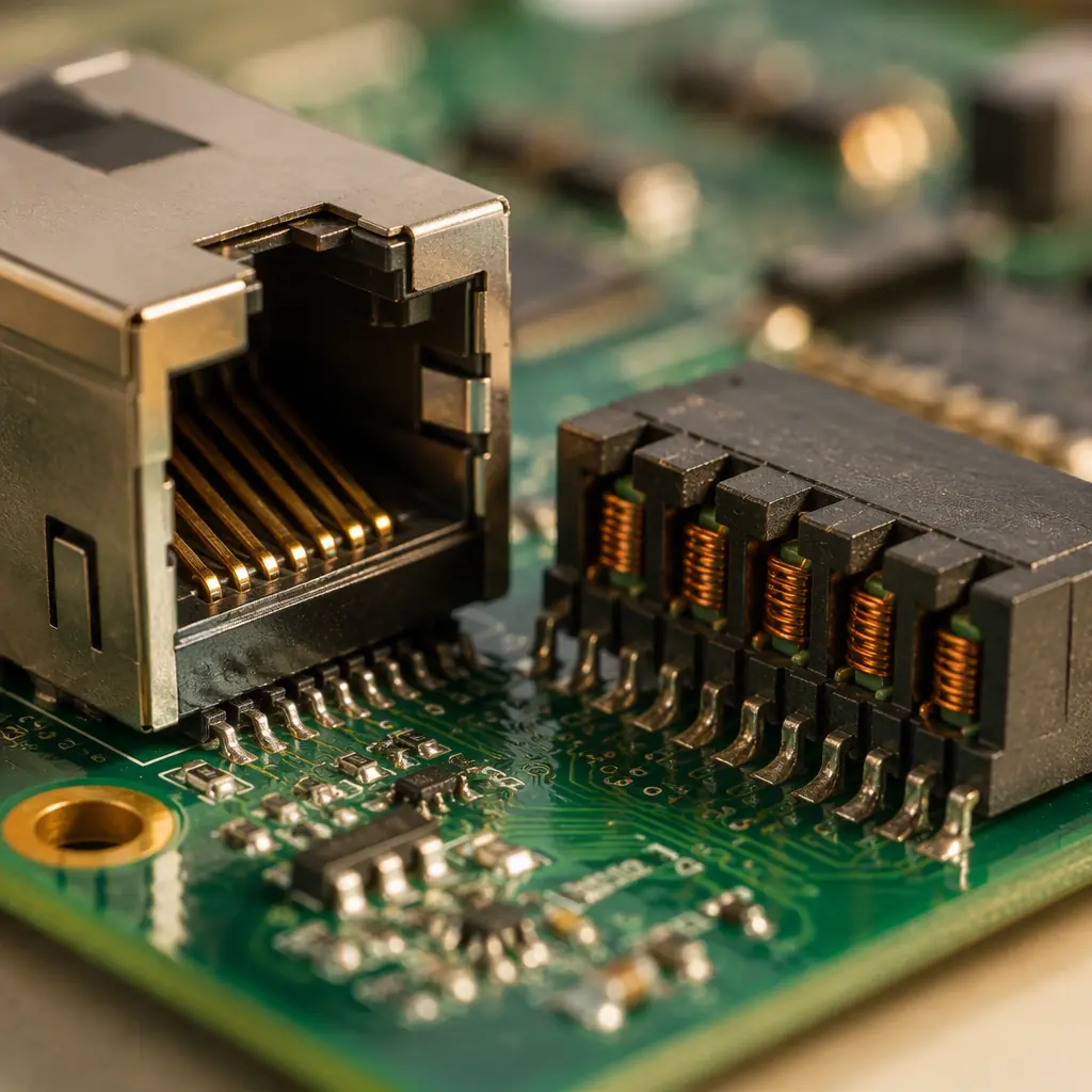
There are two common-mode filtering elements: the integrated common-mode choke inside the magnetics module, and the separation between the transformer and the connector. The choke presents high impedance to common-mode signals that would otherwise radiate. If you are failing radiated emissions at 30–100 MHz, a weak or shorted common-mode path is the first suspect. This is where EMI/EMC design and magnetics selection genuinely overlap.
On the layout, treat the choke and transformer as one functional block. Keep the primary and secondary grounds separate and only join them at the defined point (often through a 1 nF, 2 kV capacitor across the barrier). If you short that boundary everywhere you lose the isolation the part exists to provide, and you convert a cabled system into an antenna.
Design Note: The most common EMC failure at a copper port is not a bad layout of the fast signals — it is a common-mode path that was never given a controlled return. Ask your EMC engineer for a common-mode "free" answer before you commit to the board; it is far cheaper than adding a ferrite after the fact.
Bob Smith Termination and Cable-Side Common-Mode
On the cable side of the transformer, the four (or eight) pairs are centre-tapped. The classic Bob Smith termination connects those centre taps through a 75Ω network to a shared 1 nF capacitor to chassis, providing a controlled common-mode load for the cable. Modern 1000BASE-T parts integrate much of this, but the concept still governs how you lay out the cable-side components and how the shield of the RJ45 connector is tied off.
Two practical rules: do not float the cable side, and give the chassis connection a low-impedance, short path. A long, thin trace from the RJ45 shield to the chassis earthing point turns what should be a controlled termination into an unintended radiating element.
PoE Magnetics: When the Transformer Carries Power
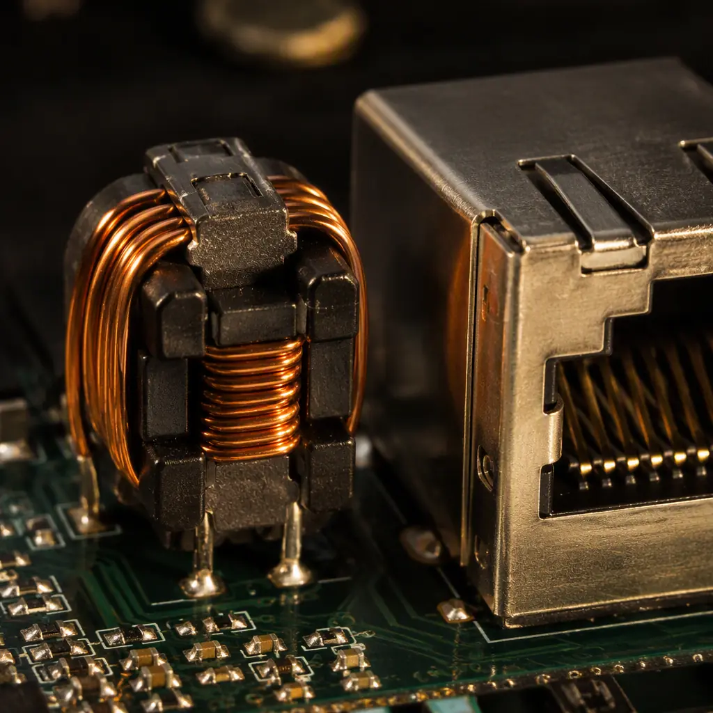
Power over Ethernet changes the game entirely for the magnetics. In PoE, the centre taps of the transformer pairs and the common-mode chokes carry the injected DC power. The magnetics must be rated for the continuous current of the class you are building to. The IEEE 802.3 classes are the practical shorthand:
| PoE class | PD power | Magnetics current rating | Typical use |
|---|---|---|---|
| 802.3af (PoE) | up to 12.95 W | ~350 mA per pair | IP cameras, sensors, readers |
| 802.3at (PoE+) | up to 25.5 W | ~600 mA per pair | Pan-tilt cameras, thin clients |
| 802.3bt (PoE++) | up to 71 W (and 90 W PSE) | 1.5 A+ across 4 pairs | LED lighting, access points, PTZ |
For 802.3bt, the four pairs are used and the current divides, so the magnetics and the board copper both need to handle the higher total. This is rarely a datasheet gotcha; it is a copper-weight and thermal one. See our PoE PCB design guide for the power-side engineering, and our trace width & current capacity guide for sizing the copper.
How a Contract Manufacturer Should Verify Magnetics
Because magnetics are cheap and small, the tendency is to let placement and reflow take care of them. But a soldered magnetics can be a dead magnetics, and a silent hit is the worst kind. Here is the manufacturing checklist you should demand.
X-ray the BGA and the leaded magnetics
Magnetic modules often use gull-wing or J-lead terminations that are hard to inspect optically. X-ray confirms wetting under the terminations and catches voids that optical inspection misses. Our X-ray inspection is a standard step on the line.
Confirm orientation and pad registration
The primary and secondary are not symmetric on many parts. A 180° placement flip swaps the isolation barrier and grounds the cable side to your chassis — a real field hazard. Automated optical inspection plus the first-article report should catch it. See our first-article inspection guide.
Run a link-quality and connectivity test
On a reference unit, do a bit-error-rate or link-margin check across the production temperature range. Continuity-only tests will not catch a marginal magnetics module. Functional + ICT/FCT coverage with a real line driver is the point where a quality-focused partner earns their keep. See our PCB testing methods guide.
Verify isolation with a hi-pot test
If your design calls for a specific isolation barrier, a dielectric-withstand (hi-pot) sample test on the production lot validates that the board and the part hold the rating. This is a routine, inexpensive check that de-risks certification.
Summary: The Magnetics Are a System, Not a Component
Treat the LAN magnetics module as a small system with a safety, EMC, signal-integrity and (in PoE) power job all at once. Pick the isolation class for the system, respect creepage and the ground boundary, keep the common-mode path controlled, size the magnetics for the PoE current, and verify the soldered result with X-ray, orientation checks and a real link-quality test. Get those right and the port is boring, which is exactly what you want.
At Huaxing PCBA we assemble IATF 16949 and ISO 9001 certified boards with 8 SMT lines, 8M placements/day, and AOI, X-Ray and SPI inspection on every line, on 32-layer boards down to 0.3 mm pitch and 0201 parts. We are happy to review your magnetics layout and tell you what will run on the line. Get a quote or ask our engineering team to look at your Ethernet port design.