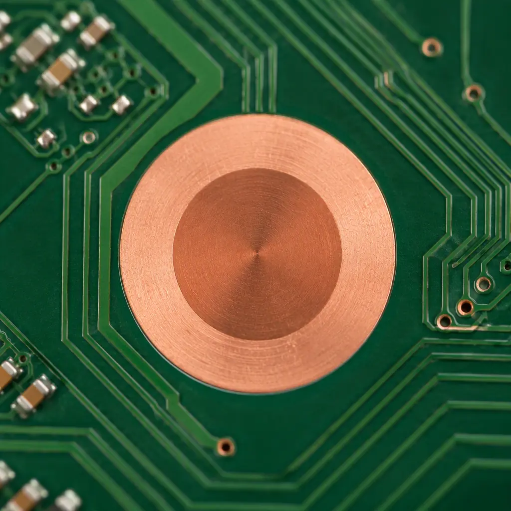
A fiducial is a small, high-contrast copper feature placed in the board substrate that a machine-vision camera can lock onto to establish the board's position and rotation before placing components. The camera finds the fiducial pattern, computes the board origin and skew relative to the machine coordinate system, then compensates so every part lands in the right place. Without it, the machine relies on board-edge detection alone, which is far less accurate — and the error grows as the board is rotated in the fixture. At Huaxing PCBA we assemble on 8 SMT lines with 8M placements/day, X-ray and AOI inspection, and we place 0201, 0.4 mm-pitch QFNs and large BGAs, where fiducial accuracy is what separates a clean first pass from a rework-heavy one. See our assembly process and Gerber files guides.
This guide covers what to design for: fiducial size, shape and contrast; solder-mask clearance; the difference between global and local fiducials; how many you need; whether double-sided boards need them on both sides; and the placement limits that keep them usable across reflow and final test.
Fiducial Size, Shape and Contrast: What the Camera Needs
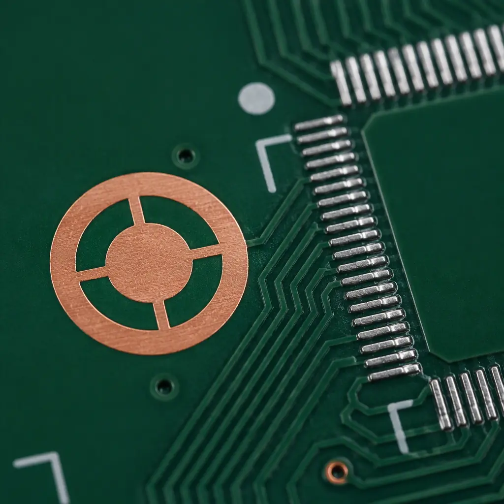
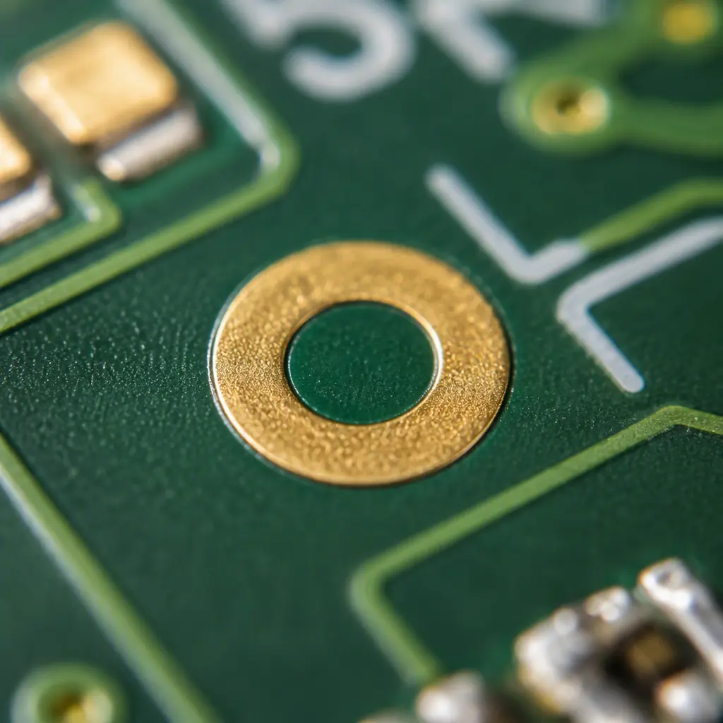
The fiducial is built as a circular copper pad with a surrounding keep-out so the camera can see a clean dark/light transition. The two numbers that matter are the fiducial diameter and the clearance around it.
| Parameter | Typical value | Why |
|---|---|---|
| Fiducial diameter (copper) | 1.0 mm (min ~0.6 mm) | Large enough for the vision system to find reliably, small enough to be unobtrusive |
| Solder-mask opening | Larger than the pad | Must expose bare copper, not mask-covered, for maximum contrast |
| Clear ring (no copper / mask) | ~1.0 mm around | Gives a clean halo so the camera edge-detect does not confuse it with traces |
| Shape | Round | Rotationally invariant — a circle looks the same from any angle |
The 1.0 mm copper pad with a generous clear ring is the de-facto standard and is what most machine-vision recipes are tuned for. If you go much smaller than 0.6 mm, the camera may struggle to find a stable centroid, especially after solder-mask and reflow. Keep the fiducial free of vias, traces and component pads so nothing breaks the contrast of the ring.
Key Takeaway: The fiducial is an exposed-copper circle with a clear ring around it. Do not cover it with solder mask, do not run traces or vias through the ring, and keep it round. If you break that contrast, the machine will misjudge the board position on every panel.
Global vs Local Fiducials: Two Layers of the Same System
There are two kinds of fiducial, and a well-designed board uses both.
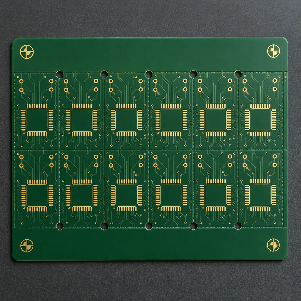
- Global (or panel) fiducials — placed at the far corners of the board or panel. They define the overall board position and rotation. Typically three to four, laid out in an asymmetric pattern (not a perfect square) so the camera can also determine the board's orientation, not just its location.
- Local (or regional) fiducials — placed close to a critical component such as a fine-pitch QFP, a QFN, or a large BGA. They let the machine re-reference that local region to compensate for local warpage or the cumulative error across a large panel. Use them when a single misaligned footprint is unacceptable.
On a large panel with many arrays, local fiducials at each array are what keep a fine-pitch part accurate at the far edge of the panel, where board distortion is largest. Our panelization and fine-pitch assembly guides cover why that matters for yield.
How Many Fiducials and Where to Put Them
The generally accepted guidance is a minimum of 3 fiducials on a board or panel, positioned so they are not collinear. Three points give the vision system a definitive fix on position and rotation. Two points still fix position but leave rotation ambiguous; one point fixes nothing useful.
At least 3, arranged asymmetrically
Place three or four fiducials so they are not on a straight line and are not a symmetric rectangle. An asymmetric pattern lets the camera distinguish a rotated board from a shifted one.
Keep a minimum distance from the board edge
Stay roughly 3.0 mm (or more) from the board's edge so fiducials survive handling, edge routing and the panel tooling. Near the edge they can be clipped by the routing or the edge rails.
Place local fiducials near critical components
For a BGA, QFN or fine-pitch IC, put a local fiducial within about 10–15 mm of the footprint so the camera re-anchors right where accuracy is needed.
Double-Sided Boards: Fiducials on Both Sides
If the board is assembled on both sides, each side is presented to the pick-and-place machine in a separate pass, and the machine cannot see a fiducial that is on the underside. So a double-sided board needs its own set of fiducials on each side. The camera uses the side-specific fiducials for that side's placement pass.
There is a subtlety after reflow, though. Reflow can warp a board enough that a fiducial measured at the start of the pass no longer reflects the local position of an already-placed part on the other side. For very tight tolerances, verify with the actual board-level accuracy rather than assuming the fiducial is a perfect proxy. Our manufacturing tolerances guide covers the board-level capability you can expect.
Fiducial Design and DFM: What We Check Before We Build
Fiducials are small, but a design error here is expensive because it is invisible until the assembly line tries to place a part. Before we quote, our engineering team verifies the fiducial layer.
Round, exposed-copper fiducial with a clean ring
We confirm the fiducial is not covered by solder mask, has no traces or vias through the clear area, and is a pad (not a drilled hole).
Three or more, non-collinear
We check the count and layout so the machine can resolve both position and rotation without ambiguity.
Fiducials and Test: They Can Do Double Duty
A well-placed fiducial can also serve as a reference for in-circuit test (ICT) probing and for automated optical inspection (AOI) registration. If you have a tightly packed board, coordinate the fiducial positions with the test and inspection plan so the same reference works across assembly, AOI and test — this avoids adding extra real estate that you do not have. Our design-for-testability guide walks through the trade-offs.
Common Fiducial Mistakes and Their Consequences
- Only one or two fiducials. Leaves rotation ambiguous; the machine can place the first fine-pitch part offset.
- Fiducial covered by solder mask. Kills the contrast the camera needs; the vision system either fails or picks a false reference.
- Traces or vias through the clear ring. Breaks the clean halo and confuses edge detection.
- Fiducials too close to the board edge. Clipped by routing or the tooling rails, so they are gone by the time the line needs them.
- No local fiducial near a BGA / fine-pitch part. The whole array inherits the global registration error.
Summary: Give the Machine Something to Lock Onto
Fiducials are a small, cheap design gesture with an outsized effect on assembly yield. Design round, exposed-copper fiducials at 1.0 mm with a clean clear ring, place at least 3 in an asymmetric pattern a safe distance from the board edge, add local fiducials next to critical fine-pitch and BGA parts, and put them on both sides of a double-sided board. If you do, your pick-and-place machine will consistently land parts where they belong — and your first article will be far more likely to be a clean pass.
At Huaxing PCBA we build IATF 16949 and ISO 9001 certified boards with heavy copper, HDI, flex and rigid-flex and up to 32 layers, and we assemble on 8 SMT lines with 8M placements/day, X-ray and AOI inspection. We can review your fiducial and placement data before you commit to a build. Get a quote or ask our engineering team about your fiducial design.